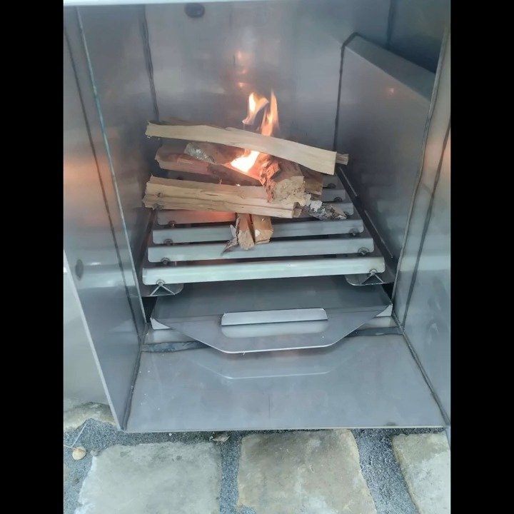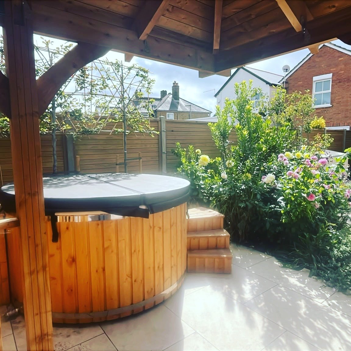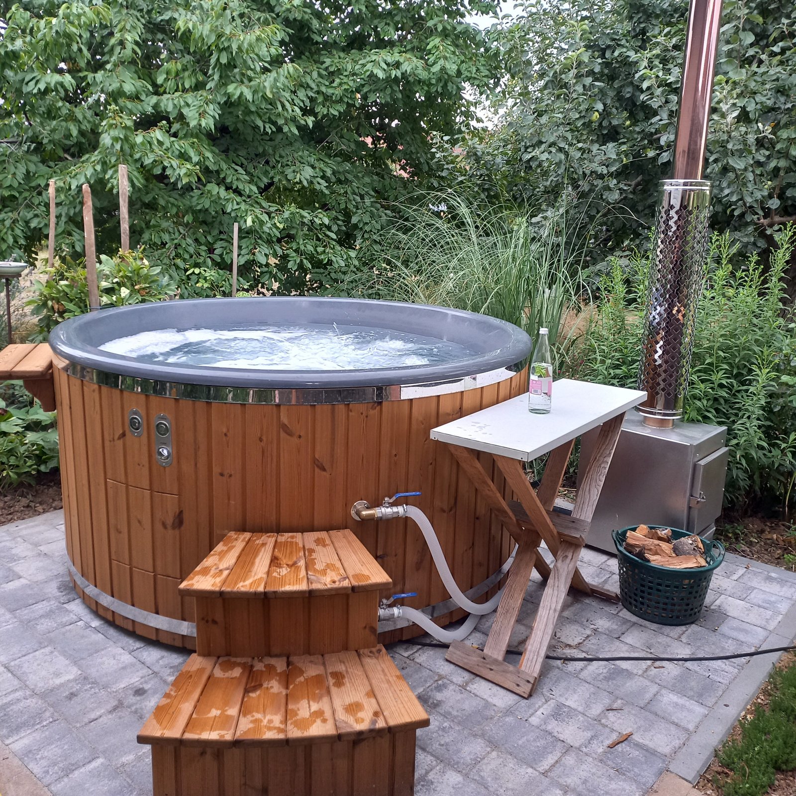

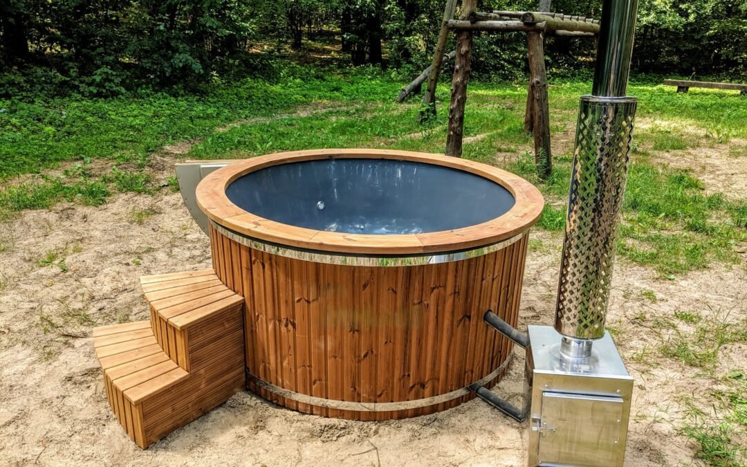
An external wood-burning stove can heat a hot tub simply and efficiently, provided water can circulate correctly between the tub and stove. In a natural-circulation installation, there is no pump to force the movement: the temperature difference and gravity do the work. Stove position, connection direction and pipe gradients are therefore essential.
Why does water circulate without a pump?
The principle relies on natural convection. Cooler, denser water reaches the stove through the lower connection. As it heats in the exchanger, it becomes lighter and rises towards the upper outlet. It then returns to the hot tub while more cool water takes its place in the circuit.
This movement seems simple, but it depends directly on the geometry of the connections. A wrongly aligned pipe, a stove too far away or air entering the circuit can slow or stop circulation. To put this circuit in the context of the whole system, also see our guide to how a hot tub works.
The stove’s two connections: do not reverse the direction
The lower connection: cold-water inlet
The connection at the bottom of the stove receives water from the tub. This inlet must remain clear so that water can enter the heat exchanger naturally.
The upper connection: hot-water return
After heating, water leaves the stove through the upper connection and returns to the tub. This pipe must encourage the natural rise of hot water without creating a point that blocks the flow.
If you are still comparing different heater positions and types, our page on hot tub stoves helps distinguish external, submerged and integrated solutions.
Three rules for an effective connection
Place the stove close to the hot tub
The length, diameter, gradient and position of the connections must follow the approved drawing for the exact stove and tub. A distance limit alone is not enough to validate thermosiphon operation. Ask for the installation drawing corresponding to the order before fixing the stove position.
The hot tub user manual helps you find the documents. For all installation dimensions, the manual and drawing supplied with your stove remain necessary.
If the planned route differs from the drawing, stop preparing the connection and have a solution approved by the manufacturer. Adding a pump is not a correction to improvise: it changes how the circuit works and its possible operating states.
Give the hot-water return a slight rise
The pipe leaving the upper stove connection must rise slightly towards the tub. This gradient helps hot water return naturally to the tub.
A completely horizontal or descending return can disrupt convection. Hot water may then circulate too slowly or remain in the stove instead of returning correctly to the tub.
Make every connection fully sealed
Pipes and connections must be secured correctly and sealed against air and water ingress. Even a small leak or air entering can disrupt circulation and reduce heating performance.
Before the first heating, inspect clamps, connections and joints. It is easier to correct a connection now than after starting to heat the water.
What happens when the connection is incorrect?
Circulation stops
If the distance, gradient or connections prevent water from circulating, the convection circuit can no longer work normally.
The hot tub heats poorly
Insufficient circulation means the heat produced by the stove is poorly transferred to the tub water. Heating becomes slow and uneven.
Pressure can rise in the stove
If hot water can no longer leave the exchanger correctly, it may accumulate in the stove. An installation that does not allow free circulation must not be used until the problem is corrected.
Checks before the first heating
Before heating, check the accessible parts of the installation while cold and compare them with the approved drawing. A visual check cannot detect every error and does not replace acceptance of the installation by a competent person.
Preparation also includes filling and venting the hot tub’s water spaces according to the manuals: a full tub does not by itself prove that the stove and every circuit contain water correctly.
- Cold inlet: water from the tub can freely reach the stove’s lower connection.
- Hot return: the upper pipe returns to the tub with a slight rise.
- Geometry: lengths, diameters, heights and gradients match the approved drawing for the configuration.
- Connections: pipes, joints and clamps are correctly tightened and sealed.
Follow the model’s shutdown procedure, keep away from hot surfaces and water, then have the installation checked after cooling. Do not disconnect, tighten or alter any connection during heating.
If the symptom is coloured liquid, the guide to brown liquid beneath the stove helps distinguish observations made when cold. Colour alone cannot establish whether it is a water leak or condensation.
Choose a hot tub designed for an external stove
Connection is much simpler when the tub, wall fittings and stove were designed to work together. If you want an external-heating configuration, the TimberIN Nordic™ External Comfort is an example of a tub designed around a stove outside the bathing space. You can also compare the full range of wood-fired hot tubs.
Frequently asked questions
Why must the upper pipe rise towards the tub?
Because heated water rises naturally. A slight upward gradient helps the hot return reach the tub and supports convection circulation.
What distance can there be between the stove and tub?
The permitted distance belongs to the model’s connection drawing, together with its diameters, gradients and heights. Do not transfer a figure from another installation or add a pump without assessment and manufacturer approval.
Can a small leak really affect heating?
Yes. A leak or air entering can disrupt water movement and reduce circuit efficiency. Connections must therefore be correctly tightened and sealed.
What signs can indicate an incorrect connection?
Water heating very slowly, circulation appearing to stop or abnormal heat accumulation in the stove are signs that require the installation to be checked immediately.